Animatronics Compliance Checklist: From Design to Deployment
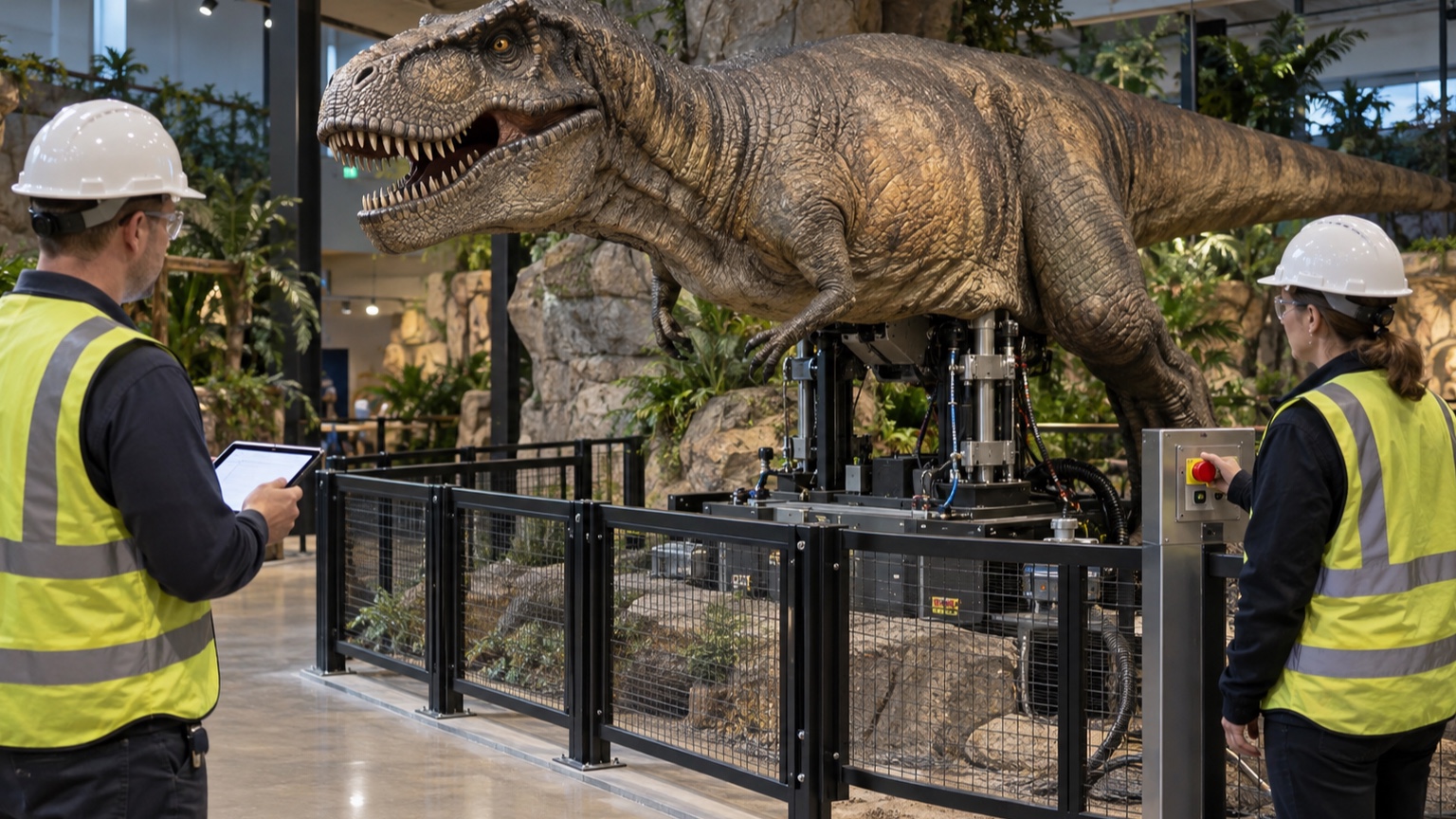
Compliance is easiest when it develops with the animatronic instead of being inspected into the project at the end. A reliable checklist follows decisions from concept through public operation: define the installation and jurisdiction, identify responsible authorities, document intended use, assess hazards, select risk controls, design the energy and control systems, verify fabrication, validate the finished machine, confirm site conditions, and hand over records that operators can actually use. The checklist is not a declaration that every listed standard applies. Requirements vary with location, venue, audience access, technology, employment setting, and contractual approvals. Nor is checking a box proof that a safeguard works. Each gate should name the evidence, acceptance criteria, responsible reviewer, unresolved issues, and approval to proceed. Used that way, the checklist exposes missing decisions early and creates a traceable safety file instead of a folder assembled after installation.
A: No. It must be adapted to the location, installation, technologies, and approving authorities.
A: During concept development, before major design commitments restrict compliant options.
A: Objective evidence reviewed against defined acceptance criteria by the responsible person.
A: No. Integration, installation, software, structure, use, and hazards still require evaluation.
A: Record them, compare ratings and safety implications, obtain required approval, and repeat affected tests.
A: No. Foundations, barriers, utilities, surroundings, and final dressing can change performance and risk.
A: A named party with a deadline and clear restriction on operation until closure where necessary.
A: Hardware revisions, software and motion versions, settings, payload, utilities, safeguards, and relevant environment.
A: After material changes, relocation, incidents, recurring faults, or updated requirements affecting the installation.
A: Whether evidence shows the installed system meets applicable requirements and its defined acceptance criteria.
Gate 1: Define Scope, Jurisdiction, and Responsibility
Begin with a short project definition: what the figure does, where it will operate, who encounters it, who employs the technicians, and who owns it after handover. Identify the authority having jurisdiction, venue reviewers, insurers, engineers, and other parties whose approval is required. Record applicable laws, codes, contractual standards, and client rules with current editions. If applicability is uncertain, assign the question and resolve it before design advances.
Responsibility must be specific. Name who performs risk assessment, structural design, electrical design, safety-control design, fire review, fabrication inspection, software verification, installation approval, training, and final acceptance. A contract can distribute work, but a responsibility matrix prevents essential tasks from disappearing between vendors.
Gate 2: Capture Requirements and Intended Use
Write measurable requirements for motion, payload, speed, force, travel, duty, utilities, environment, audience distance, accessibility, sound, lighting, and maintenance. Define automatic, manual, setup, service, transport, and emergency modes. Include foreseeable misuse: reaching, climbing, misplaced objects, repeated resets, bypass attempts, and operation after a warning.
Identify assumptions that future decisions depend upon. Examples include a fixed barrier, indoor humidity range, trained operator, dry compressed air, maximum costume mass, or floor strength. Give each assumption an owner and a verification point. An assumption that cannot be confirmed at deployment must not remain hidden inside the design.
Create a requirements trace linking each obligation to a drawing, calculation, procedure, inspection, or test. Traceability reveals requirements that have no evidence and tests that do not correspond to a stated need.
Gate 3: Assess Hazards Before Freezing Geometry
Review the complete lifecycle and identify mechanical, electrical, thermal, fire, pressure, ergonomic, structural, noise, material, software, and maintenance hazards. For each hazardous situation, identify exposed people and possible harm. Estimate and evaluate risk using the project’s selected method. Record existing controls separately from proposed ones so the design team can see what remains open.
Apply inherently safer design first. Remove a motion, reduce mass or energy, reshape an edge, change a linkage, move a mechanism away from access, or design out a trapped space. Then select guards, separation, interlocks, monitored limits, containment, and other engineering measures. Procedures, training, and warnings communicate residual risk but should not carry a burden that practical design measures could remove. Reassess after applying controls. Every measure can introduce a new issue: a barrier may affect evacuation, a brake may create heat, a counterweight stores energy, and an enclosure may block cooling. Keep unresolved actions visible and prevent the project from passing the gate when a critical control remains undefined.
Gate 4: Approve the Technical Design
Structural documents should define load paths for weight, acceleration, stopping, imbalance, wind where relevant, transport, maintenance, and credible faults. Specify materials, connections, anchors, foundations, allowable deflection, inspection points, and any secondary retention. Coordinate structure with scenery so cosmetic work does not conceal required access or compromise a guard.
Electrical and fluid-power designs should show supplies, disconnects, protection, grounding or bonding, isolation zones, pressure control, stored-energy release, conductor or hose ratings, environmental protection, and identification. Confirm that components are used within manufacturer instructions and suitable for the location.
Safety functions need written specifications: initiating condition, required response, safe state, reset, restart prevention, diagnostics, fault reaction, interfaces, and required performance. Review common dependencies such as shared power, brackets, cables, software, and network paths. Approve the verification and validation plan before fabrication makes changes costly.
Gate 5: Control Procurement and Substitutions
Purchase records should identify safety-critical specifications rather than only vendor part numbers. Capture ratings, environmental limits, materials, certifications where required, and configuration. On receipt, verify identity and condition. Protect sensitive components during storage and record shelf-life or preservation needs.
Substitutions require technical review. A replacement motor with similar power may have different inertia or braking. A hose may share dimensions but differ in pressure, bend radius, fire behavior, or fluid compatibility. A sensor may fit while changing diagnostic coverage. Document the comparison, approvals, drawing updates, and tests affected. Vendor assemblies do not remove integration responsibility. Obtain instructions, declarations, test information, software tools, and maintenance requirements early enough to incorporate them into the system and final handover.
Gate 6: Inspect Fabrication Before It Is Hidden
Use staged inspections for frame geometry, welds, fasteners, cable and hose routing, grounding, guards, stops, sensor targets, labels, and service access. Inspect areas before skins, foam, scenic panels, or insulation conceal them. Photographs can preserve routing and attachment details, but they supplement rather than replace defined acceptance criteria.
Control nonconformities. Record what differs, evaluate the consequence, approve repair or use-as-is disposition through the appropriate authority, and update the design record. Informal field fixes are dangerous when later drawings show a condition that was never built.
Check workmanship under motion. Adequate slack at home may become tension at full travel; a bundle can rub only during combined-axis movement. Verify clearances through the planned envelope at reduced energy and stop when behavior differs from the approved design.
Gate 7: Commission in Controlled Steps
Before energizing, inspect assembly completeness, remove loose objects, install temporary safeguards where permanent ones are unfinished, confirm isolation devices, and brief the team. Establish an exclusion zone and test plan. Start with individual axes, reduced speed, reduced force or pressure where feasible, and conservative limits.
Progress from direction and sensor checks to travel, load, coordinated motion, dressed motion, duty-cycle operation, and fault testing. Record settings rather than tuning by memory. Measure current, pressure, temperature, stopping behavior, and other acceptance variables under representative conditions. Commissioning problems must return to controlled correction. Do not overcome binding with more pressure, extend a limit to hide lost travel, or suppress a fault without understanding it. Update the hazard assessment when behavior or design differs from expectations.
Gate 8: Validate Safeguards and Documentation
Validation confirms that risk-reduction measures meet their specifications in the finished configuration. Test guards, barriers, interlocks, safety-related controls, emergency stops, isolation, stored-energy controls, reset, restart prevention, alarms, and relevant fault responses. Use qualified personnel, calibrated instruments where needed, safe test methods, and predetermined acceptance criteria. Review documents against the as-built system. Schematics, programs, parameter files, drawings, parts lists, inspection instructions, and risk records must agree with reality. Verify backups by opening or restoring them in a controlled environment. Close test failures and repeat affected validation.
Gate 9: Reconfirm Everything at the Site
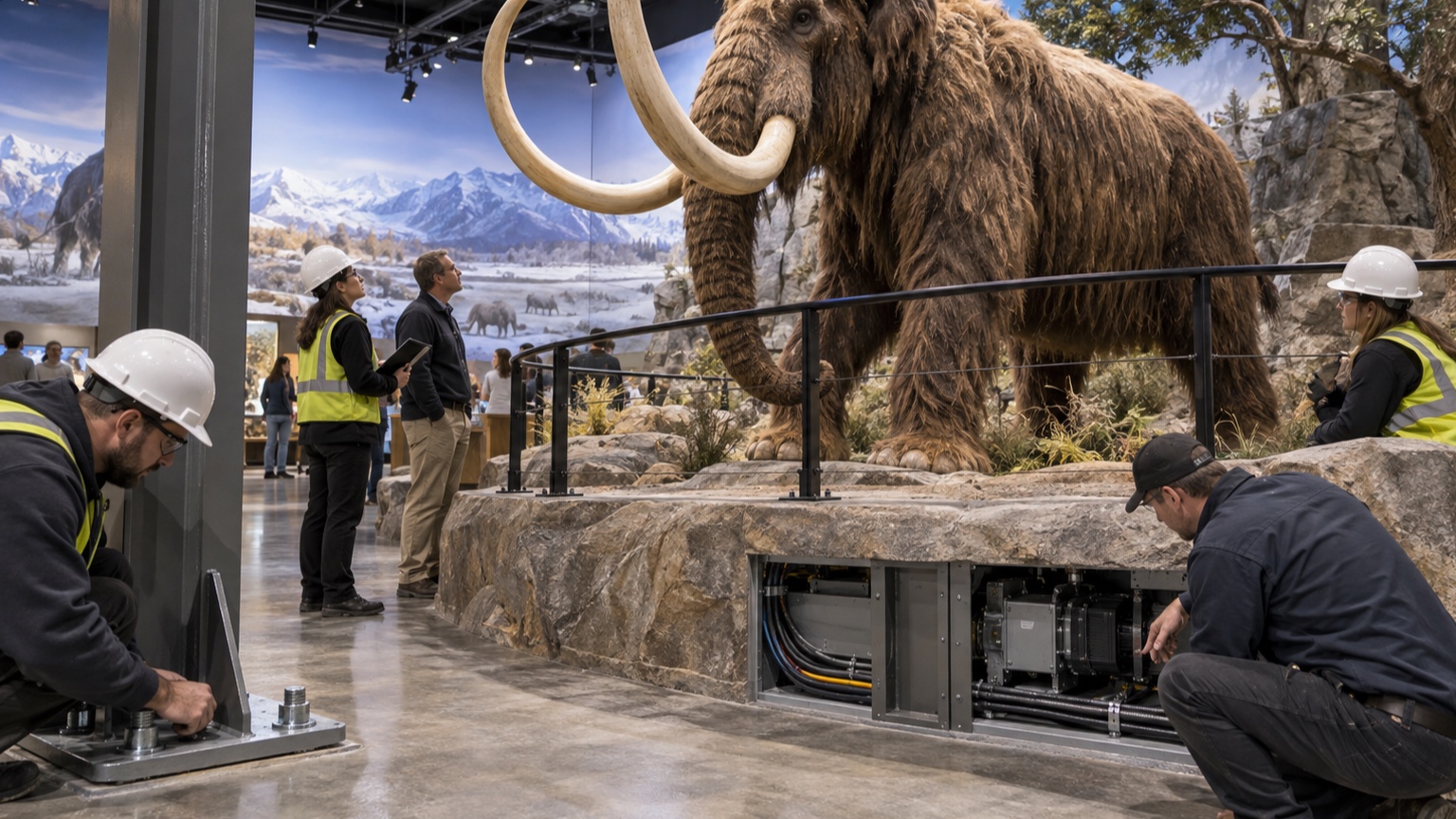
Inspect transport damage, support surfaces, anchors, level, utilities, grounding, drainage, ventilation, barriers, viewing distances, emergency access, lighting, and interfaces with nearby equipment. Install using approved procedures and record field deviations. Recheck structural and service clearances after scenery and public furnishings are placed.
Run representative operation with final skins, costume, show files, payload, utilities, and ambient conditions. Verify stopping, homing, temperatures, pressures, current, leaks, noise, and motion clearance. Repeat safeguards affected by transport or installation. A shop result cannot approve a site condition that did not yet exist.
Coordinate operations: queue layout, cleaning, opening checks, fault response, evacuation, and communication. Confirm staff can see indicators, reach emergency devices, isolate energy, and summon technical support without entering hazards.
Gate 10: Conduct an Operational Readiness Review
Before opening, gather the people who will operate, maintain, supervise, clean, and manage the space. Walk through a normal start, show cycle, ordinary stop, detected fault, emergency intervention, evacuation condition, maintenance isolation, and return to service. The review should reveal whether written procedures match staffing, sight lines, access, language, lighting, noise, and the time available during real operations. Correct the system or procedure when staff must improvise around a hazard.
Test communication paths. Operators need to know who receives a technical call, who controls the surrounding area, and who decides that operation may resume. Provide clear escalation criteria for abnormal sound, smell, temperature, leakage, repeated faults, barrier movement, guest contact, or damage. Repeated resetting without diagnosis should be prohibited. If remote monitoring is used, define which conditions require an on-site inspection rather than assuming a healthy screen equals a healthy machine.
Confirm the maintenance workflow with the actual tools and access equipment. Verify that isolating devices can be reached and locked, stored energy can be dissipated or restrained, raised assemblies can be supported, and removed panels can be handled safely. Ensure replacement parts, consumables, special tools, lifting fixtures, test equipment, and approved lubricants are available. A maintenance instruction is incomplete if it depends on equipment the owner does not possess.
Review emergency coordination with venue leadership. An animatronic incident may affect crowd routing, fire systems, medical response, security, or utilities. Staff should know whether an emergency stop removes only motion or also affects lighting, sound, ventilation, or neighboring effects. Practice the response without creating a new hazard. Record findings, assign corrections, and repeat affected portions before authorization to open.
Gate 11: Handover for Safe Operation
Deliver operating limits, normal procedures, pre-opening checks, fault responses, shutdown and isolation instructions, maintenance schedules, rejection criteria, spare-parts data, drawings, schematics, software backups, validation records, and outstanding-action status. Train operators and maintainers for their different roles, then record competence or completion as required.
Define who may reset faults, change choreography, adjust pressure, replace safety-related components, modify guards, or approve substitutions. Establish incident, near-miss, defect, and change reporting. Set dates or usage triggers for inspection and review.
Gate 12: Preserve Compliance After Opening
Compliance is a maintained condition. Audit inspections, tests, bypasses, repairs, recurring faults, and documentation. Reassess when the figure is relocated; barriers, payload, motion, software, utilities, components, or environment change; an incident occurs; or requirements affecting the installation are revised.
Set a formal review interval even when no major event occurs. The review should confirm that responsible contacts, standards references, training, spares, backups, inspection criteria, and emergency procedures remain current. Compare the installed figure with its drawings and approved configuration. Small undocumented alterations can accumulate until the original validation no longer describes the machine in service.
Use operating evidence to improve the system. Trends in current, backlash, leakage, temperature, faults, or reset frequency can reveal loss of margin. Treat repeated intervention as a signal, not normal inconvenience. A disciplined change process keeps the approved configuration recognizable while allowing necessary improvement.
The final checklist is therefore not a stack of yes-or-no answers. It is a chain of evidence showing that requirements were identified, hazards reduced, designs reviewed, construction inspected, functions validated, site conditions confirmed, people prepared, and changes controlled. That evidence gives owners a defensible basis to open the installation—and a practical method for keeping it safe afterward.